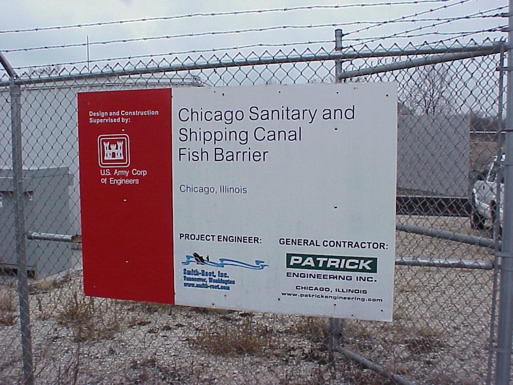
Chicago Sanitary and Ship Canal I
Smith-Root provided the technology for this demonstration barrier to prove the effectiveness of an electrical barrier to prevent invasive species movement.- Location: Romeoville, Illinois
- Commissioned: 2002
- Type: Waterway
Project description
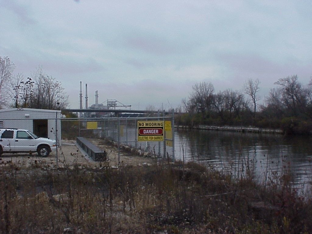
The Chicago Sanitary and Ship Canal was constructed in 1900 to enable the city of Chicago, Illinois to get rid of wastewater without polluting its water source, Lake Michigan. It is the only water connection between the Great Lakes and the Mississippi River system. In recent years, treatment of the wastewater has made the canal habitable to fish. With that improvement comes the threat of invasive species moving through the canal, in particular round goby into the Mississippi, and asian carp into the Great Lakes.
Because the canal carries much private boat and commercial barge traffic, and affects the Chicago drainages, it is not politically feasible to close the canal. An electrical barrier was proposed so that canal traffic could continue without impedance.
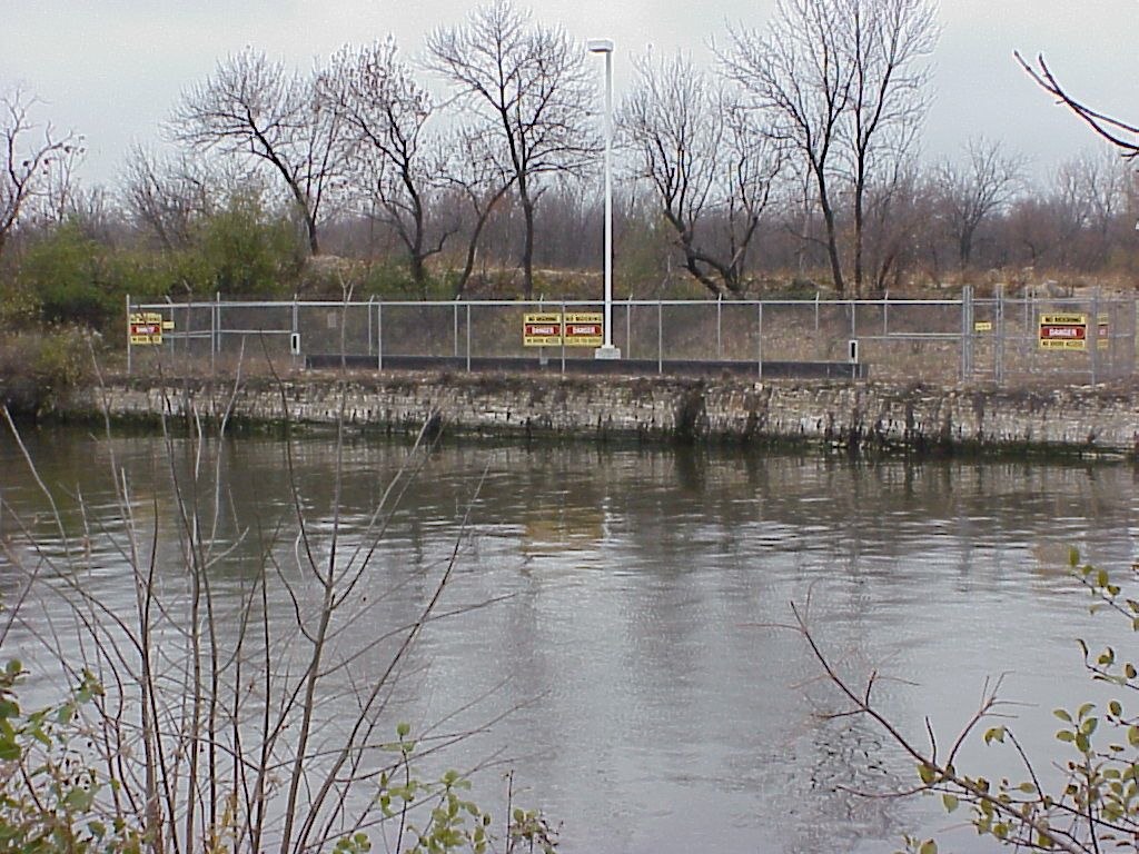
Smith-Root designed and constructed this demonstration Barrier I in 2002. Its electrodes are of continuous wire rope passing through angled drill holes through the banks and stretching across the bottom, supported on concrete sleepers.
Biologists tested the barrier using surrogate tagged fish and found it to be effective.
It has operated continuously since 2002, providing back-up to later Barriers IIA and IIB. Its electrodes have been replaced once.
Particular challenges were the size of the canal, the need for a long field because of the barges, high and variable conductivity of the canal water, canal water temperatures, and the unavailability of the canal walls because of barge movements.
Services provided
- Coordination with owner U.S. Army Corps of Engineers, Chicago District
- Coordination with fish researchers
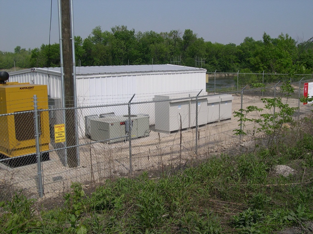
- Civil engineering for the barrier layout, structural design of the building, electrical design of the pulsator and power supply systems
- Prime contracting for construction, installation, and commissioning
- Continued monitoring of electrical barrier remotely to ensure system integrity
- Complete annual maintenance of electrical barrier
Site characteristics
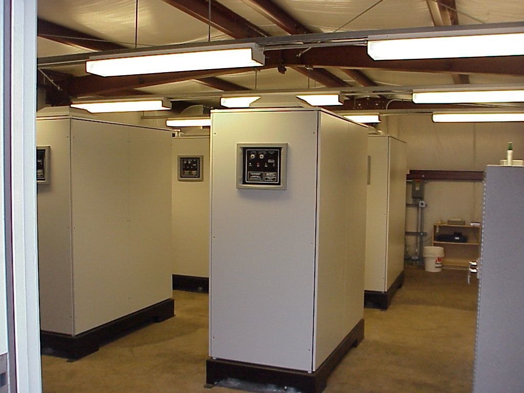
- Pulsators: Custom
- Pulsator Qty: 4
- Power Output: 350kW max.
- Water Depth: 25 feet
- Waterway Width: 160 feet
- Water Velocity: (-1)-3 ft./s
- Conductivity: 3500 µs;/cm max.