Wilkins Slough
Smith-Root participated in a testing program to evaluate alternatives to physical screens preventing salmon smolts from entering irrigation canal pumps. The electric barrier achieved more than 90% efficiency.- Location: Colusa, California
- Commissioned: 1995
- Type: Experimental
Project description
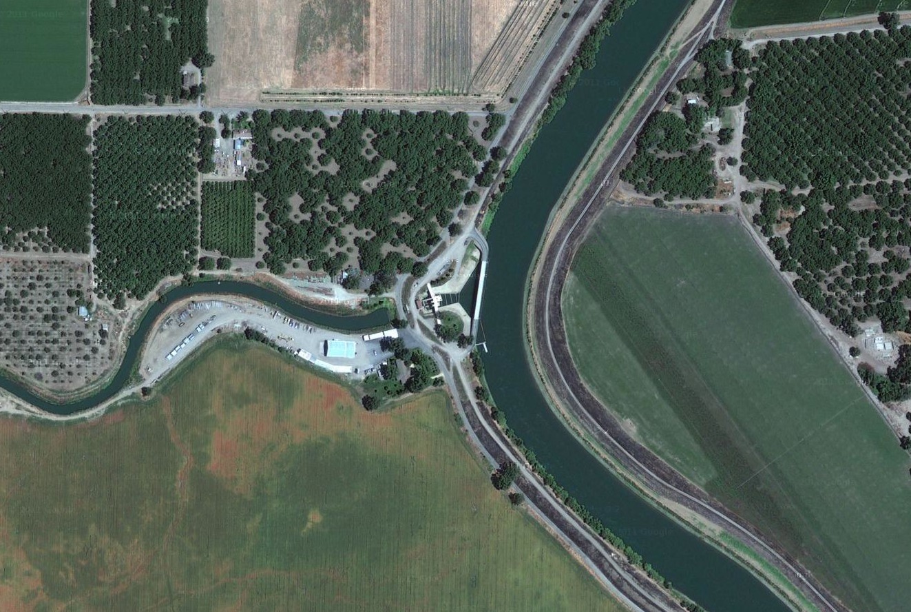
In a study to find alternative ways to prevent fish from being drawn into irrigation pumps, Smith-Root, within constraints of the program from Reclamation District 108 and U.S. Bureau of Reclamation, designed and constructed a temporary array across the forebay leading to a pumping station drawing irrigation water from the Sacramento River. The experiment continued over four years.
The electrical barrier consisted of aluminum vertical droppers in various arrangements suspended from a long floating dock.
Test batches of smolts were released into the upstream streamline that turned into the forebay. A definite repelling action from the electric field was observed. 1996 statistical results showed that the barrier reduced the number of smolts passing through the forebay by more than 90% (RD108 Funding Proposal 7-28-97). Strobe lights and a separate sound system were ineffective.
Several aspects of the test configuration were less than ideal. The field was oriented at 90 degrees from the water motion: fish were not exposed fully head-to-tail. Uncontrolled water velocity resulted in concentrated entraining flows up to 2.5 ft./s. And many of the test smolts were partially incapacitated from handling, including dyeing.
Because National Marine Fisheries Service rules required 95% efficiency, a permanent electric barrier was not installed. Instead, there are now screens requiring the usual constant cleaning and maintenance.
Given the circumstances, Smith-Root considers this to be an affirming study. Efficiencies could have been improved with a better configuration.
Services provided
- Coordination with U.S. Bureau of Reclamation and Reclamation District 108
- Barrier concepts, configurations, and adjustments
- Electrical and electronic design of the pulsators and power supply systems
- Supply of electronics
Site characteristics
- Pulsators: 1.5kVA POW
- Pulsator Qty: 12
- Power Output: 18.0 kW max.
- Water Depth: 10-30 feet
- Waterway Width: 190 feet
- Water Velocity: 0.08-2.5 ft./s
- Conductivity: 200-1800 µs/cm max.